Category: Projects

My portfolio of real work. Technology, papers, tex, latex conversions to PDF, the good stuff.

  • DIY Today: Push Button PCB Ordering, Wow!

    DIY Today: Push Button PCB Ordering, Wow!

    My Early Fascination With Electronics

    When I was a child, I was obsessed with anything electrical and anything push button. I had a toy train transformer and would unravel fine copper wire to make tiny filaments that heated up and caught fire. My dad even helped me build a real electric motor on a piece of shelving board. The armature was a hard rubber ball with 16‑penny nails wrapped in copper magnet wire. We made brushes from a tin can using tin snips. We powered it with the train transformer. No push buttons yet — just pure DIY ingenuity.

    Building My First Radios

    I made a crystal radio with my grandfather that actually worked. Sitting on the bathroom floor in Portsmouth, Virginia, I heard a local AM station using an antenna wire out the window and a ground clipped to the sink drain. Later, I built more radios from kits. My grandfather took me to RadioShack often. I loved that place, but I always struggled with the connections between components — the “network” of the design.

    Learning Schematics and Early PCB Attempts

    I learned to read schematics before I ever went to college for electrical engineering. Kits were easy because the PCB was already made. But if you wanted to experiment, options were limited.

    My first breakthrough was using copper‑clad board and making large pads to hold components. It worked, but it wasn’t permanent or production‑ready.

    The next method was blocking traces with rub‑on stickers or a Sharpie and soaking the board in chemicals. Not exactly kid‑safe, and definitely not efficient.

    Life, Work, and Returning to DIY Electronics

    Eventually I grew up, went to college, changed schools, and ended up building nuclear submarines — doing piping system design for the Navy’s underwater fleet. Electronics took a back seat.

    Fast‑forward to today: I’m building a 7‑band HF transceiver from scratch. KiCad became my tool of choice for schematics and PCB layout. Each component lives in a private GitHub repo. After finishing a schematic, I open KiCad’s PCB editor and arrange the components. I’ll write more about that workflow soon.

    I design the PCB myself — DIM, not push button AI. When the PCB is complete, I generate Gerber and Drill files. These files define the exact requirements for manufacturing.

    From Old‑School Etching to Modern PCB Manufacturing

    This is a long way from sitting on the back porch with copper board, etching chemicals, and hand‑drawn traces. Today, you zip your Gerber and Drill files and send them to any PCB manufacturer.

    Enter Push‑Button PCB Ordering With PCBWay

    Since I use PCBWay as my PCB supplier, I discovered a new plugin for KiCad: PCBWay Plug‑In for KiCad

    This plugin changes everything.

    How the Push‑Button Workflow Works

    • The plugin adds a PCBWay icon to KiCad’s toolbar.
    • When your PCB is ready, you click the icon.
    • KiCad automatically uploads your Gerber and Drill files to PCBWay.
    • The PCB order page opens with everything pre‑loaded.
    • PCBWay recommends reviewing the files, but mine were perfect.

    It truly feels like push‑button PCB ordering. It is.

    Before the Plugin

    I used to:

    1. Export Gerber and Drill files manually
    2. Verify all files were present
    3. Zip them
    4. Upload the zip to PCBWay
    5. Validate the order

    Now it’s one click.

    Keeping Manufacturing Files in GitHub

    The plugin writes the files to the project directory, which is perfect — they get committed to Git and stored with the project. Clean, organized, and version‑controlled.

    Follow the Freedom7 Build

    I’m building a real HF SSB transceiver from the ground up – no kits, no shortcuts, and no hiding the hard parts.

    If you’re interested in how this system comes together over time, follow the full build here:
    https://kr4bad.com/category/the-build

    Not everything fits into a single build. For additional insights, experiments, and lessons learned:
    https://kr4bad.com/field-notes/

    Follow the build as it happens:
    https://kr4bad.com/?subscribe=1

    Looking for some background?
    https://kr4bad.com/about/

    Comments and discussion are always welcome:
    david [at] kr4bad-dot-com

    73,
    KR4BAD David
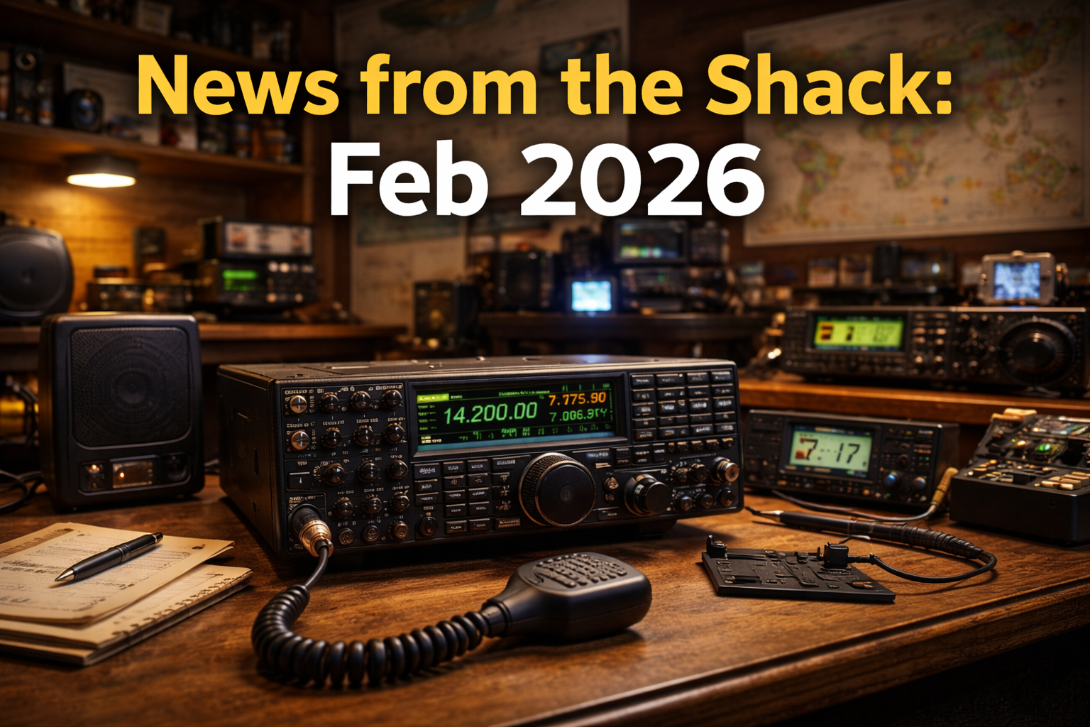
  • Good News from the Shack: Feb 2026

    Good News from the Shack: Feb 2026

    KR4BAD’s Operating Saga

    Problem

    While I’m building my own Freedom7 HF Transceiver at the bench or in the shack, I’m also a HAM operator. I love both HF and 2 meter. I renewed my old HAM license KJ4GIZ with KR4BAD. I’m not the bad guy but I do find that my new call is memorable. People talk about it, make mention of the BAD part.

    KR4BAD

    My operator problem is the huge expense all over again and based on my interests. I like 2 meter and HF. So I needed new radios. The VHF/UHF one I had was terrible and has something wrong with it. It was 25 watts but I don’t think it was pushing anything near that. What would I get? And, when?

    I wanted to do POTA hunting as soon as possible because I could sit on the front porch, weather permitting, and log QSOs with people at US parks.

    I bought a couple Baofeng HTs and gave one to my oldest son. He likes to listen while he doesn’t study for his ticket. That’s a problem for another day.

    The HF problem was CW vs. SSB. I had a couple of CW-only radios by TenTec but nothing to do single side band (SSB). And, I could only remember CQ on the key. That’s it. I now needed to find an economical solution for an HF radio, preferably something I could take on a POTA activation.

    That would be my problem(s). I needed a solid 2-meter radio to talk with my repeater friends and a decent HF radio for phone work.

    Early Success

    The glimmer of success came for me by building my own 2-meter ground plane with 5 heavy copper wires and a SO-239 cabinet mount connector. I was able to mount it on a microphone stand that I’ll discuss later. A short coax and I could sit in a chair using my Baofengs in the living room or my shack.

    My HF radio was then just a discussion with a friend that got a Xiegu G90 from AliExpress or Alibaba. The G90 was 20W but would do HF with CW, Data, and SSB (Phone). And, at 20W I could do LiFePO4 batteries and not need a power supply. Now I save my money.

    I later went to the RARSFest at the NC state fairgrounds and got an iCom IC-208H VHF/UHF dual-band mobile radio. That would get me on the air with my friends. And, my 12AH LiFePO4 battery would run this rig for several days when I was checking in on evening nets. I also used that microphone stand, I spoke about earlier, to install a new J-Pole I purchased from KB9VBR.

    I finally had the cash to purchase a Xiegu G90 and also put a 10-40 meter long wire (EFHW) in the pine trees in my front yard. I was a technician class then and did 10 meter a bunch. I’m now general and do more but usually it’s 10-40 SSB and 10-40 FT4/FT8 (Data).

    Setback

    I offered to be net control for the Sunday night JARS net on 147.270, My iCom IC-208H was going to go dead on me mid-net at some point if I didn’t order a power supply or find another solution for my hosting the net. My Freedom7 radio is my monthly budget and I’ve been pushing hard to get the receive side working. No ready cash and an obligation to do this presented a problem.

    My second setback was the purchase of a Yaesu FT-990 100 watt HF rig from a friend in my radio club. He was selling it for the wife of a deceased friend (silent key). I can’t test it really on my good antenna but I’ve tried it and made contacts using a portable vertical, the JPC-12. I didn’t realize at this time that the VFOs had drifted and were inaccurate.

    Crisis

    I’ve actually had two crisis situations this month. First, the FT-990 should be repairable and I attempted the repair with no luck at all. I found someone semi-local to work on it but he said he didn’t know how to work on radios in that time boxing … around 1994. It was like my having a 100 watt HF rig wasn’t going to happen.

    I thought I had a charged up battery and had been using my iCom mobile successfully as a base station when one of the HAM legends pitched in the net with “comment” and proceeded to tell me my audio sucked and here’s how to fix it. Bummer, because my radio didn’t have these tweaks. I basically didn’t sound like a radio announcer or the other loud mouths in the group. I’m generally somewhat quiet but now I need a real voice in the shack.

    Recovery

    Time to kill two birds with one stone. My friend John, KM4JB has a Yaesu FT-991a and guess what it does? It’s a shack in the box so to speak. It does UHF/VHF and HF. I’m broke now but I solved both problems. Last night I did 100 FT-8 contacts from around the world on 40 meters. And, after John sent me settings for the microphone equalizers, I’m sounding like your local country music announcer on FM radio while sitting in my humble shack. I have peaked the summit.

    shack in a box

    Better Place

    Am I in a better place all around as a HAM radio operator? You bet I am! I now have a radio that does it all and I can say that I have proper tools. I had to purchase a power supply for the radio and also increase the rating on my EFHW. I replaced the unun and increased the wire gauge (14 AWG). I am also finding my voice within the JARS club and on the radio.

    My About page provides the background of the Freedom7 HF Transceiver project.

    If this story resonates, comments are welcome. You can also reach me at david [at] kr4bad-dot-communications. no com.

    And if you believe understanding our radios matters more than sealed boxes, you can subscribe here:
    https://kr4bad.com/?subscribe=1

    73
    KR4BAD
    David

    Why This Article Uses the “No Easy Way” Story Model

    This post follows the No Easy Way structure from Steve Rawling’s Pipdeck Storyteller Tactics:

    1. Problem — New license, no radios
    2. Early Success — Baofengs, some coat-hanger wire antenna, and a Xiegu G90
    3. Setback — Weak operations and no real shack environment
    4. Crisis — Purchased 100W radio is not working and my 2-meter broadcasting is weak at best
    5. Recovery — New Yaesu FT-991a
    6. Better Place — Finding my place within the JARS club and my voice on the radio

    The climb isn’t finished — but HAM life moves higher up the mountain.

  • Good News from the Bench: Feb 2026

    Good News from the Bench: Feb 2026

    The Freedom7 HF Transceiver Saga

    Problem – Starting the Climb

    This maker has decided to prepare a comprehensive posting each month, to journal the progress of my Freedom7 Transceiver at the bench. I am also doing one called, “News from the Shack” as well.

    The goal is simple, but not easy: build something real, understand it deeply, and share the lessons along the way — including the mistakes. This month’s focus has been the receive-chain, specifically a low-noise amplifier (LNA) and revisiting my band-pass filters.

    Nothing about this process has been straightforward. Designs change. Assumptions fail. And every step forward seems to reveal two more things that need attention.


    Early Success — Momentum Builds

    This month I completed the design, assembled the components, and tested a low-noise amplifier at the bench. I think the design changed about three times, and while I support fast failures, I now have a working LNA.

    low-noise amplifier

    I also returned to the band-pass filter(s) and redesigned them on paper as Butterworth modeled 3-pole, series-coupled textbook filters. My choice of components leaned toward larger air-core inductors with high-Q values. The capacitors were carefully selected as well, and two had to grow beyond the 0805 packaging because I couldn’t get the values I needed due to dielectric material limitations. I forget the exact package, but it was basically the next size up physically. I’ll achieve my maker title soon I’m sure.

    On paper — and even in simulation — things were starting to look good.


    Setback — When Reality Pushes Back

    Lessons learned always come from mistakes, and I plan to document the detailed LNA design in another posting. I’ll say here that the design leaned heavily on reference material: books, PDFs, posts, AI, and anything online I could get my hands on.

    The overall design was modeled using LTSpice over several iterations. Change something, simulate again, refactor, repeat. LTSpice is a great tool for initial design, and eventually I had results that looked promising.

    That’s when I made the classic assumption:

    “I’m ready for the breadboard.”

    Wrong.


    Crisis — Under the Big Top

    My attempt at a breadboard solution was an utter joke.

    When I connected my scope, I wasn’t looking at a clean RF design — I was under the big top at the circus that just came to town. Noise everywhere, instability, and behavior that simulation never warned me about.

    That moment forced a realization:

    This design would have to be tested in its final form — on an actual PCB, possibly with an RFI shield — not floating on a breadboard, with parasitic capacitance, and with an array of jumper wires (little antennas) like some classroom experiment.

    It was a humbling checkpoint. And, now I know, “don’t do that!”


    Recovery — Iteration Becomes the Way Forward

    The band-pass filters went through multiple iterations, both on paper and PCB. The LNA followed the same path. One clear solution moving forward is to embrace the iterative mantra:

    Design. Build. Test. Refactor. Repeat.

    Simulation gets you started. Reality teaches the lesson.

    My next component will be a very stable and accurate variable frequency oscillator (VFO), or local oscillator, slated for March. I have the start of a schematic and have identified an extremely stable and low-noise square-wave solution using a more expensive chip than the common Si5351a many hobbyists use.

    This part of the climb feels different — less guessing, more informed decisions.


    Better Place — Higher on the Mountain

    Each month’s progress brings me closer to something bigger than just a radio. This journey is about understanding, building, and hopefully inspiring others to step away from black boxes and toward real RF knowledge.

    Stay tuned and come back, y’all.

    Please check back periodically and watch my progress here. I welcome WordPress subscribers. I’m doing this for myself, yes — but also to spark interest and hopefully influence younger generations to become Makers too.

    My About page provides the background of the Freedom7 HF Transceiver project.

    If this story resonates, comments are welcome. You can also reach me at david [at] kr4bad-dot-communications. no com.

    And if you believe understanding our radios matters more than sealed boxes, you can subscribe here:
    https://kr4bad.com/?subscribe=1

    73
    KR4BAD
    David


    Why This Article Uses the “No Easy Way” Story Model

    This post follows the No Easy Way structure from Steve Rawling’s Pipdeck Storyteller Tactics:

    1. Problem — Beginning a complex RF journey with no shortcuts
    2. Early Success — Working designs and encouraging simulations
    3. Setback — Breadboard assumptions fail
    4. Crisis — The “circus” moment on the oscilloscope
    5. Recovery — Iterative engineering becomes the method
    6. Better Place — Greater understanding and forward momentum

    The climb isn’t finished — but each iteration moves higher up the mountain.


  • Collaborators, innovators, come one, come all: Join My Revolutionary HF SSB Transceiver Project

    Collaborators, innovators, come one, come all: Join My Revolutionary HF SSB Transceiver Project

    Over the past year, from a desk in my home in Fuquay Varina, North Carolina, I’ve been building a high-performance HF SSB transceiver from scratch. This Freedom7 HF Transceiver project has been a great journey but I need collaborators. Here’s the reality.

    One person.
    No team.
    No funding.
    No company.

    In that time, I’ve designed multiple microcontroller systems, written embedded C++ code, completed two full versions of receiver-chain band-pass filters, implemented seven switched BPFs on the input side, built encoder-driven VFO control with selectable step sizes, and displayed live frequency data on a working front panel — and that’s just part of the story.

    This is not theory.
    This is real hardware, real software, and real progress.

    And I need help.


    “I Could Never Do What You’re Doing”

    When I share this project with friends in my radio club, the Johnston Amateur Radio Society (JARS), I often hear the same thing:

    “I could never do what you’re doing.”

    I want to say this clearly and respectfully:

    That belief is wrong — and it’s holding something back.

    Most people assume that helping with a project like this means you have to be an RF expert, a programmer, or a career engineer. That’s simply not true. World-class systems are not built by one skill set — they’re built by people with different strengths working toward the same goal.


    Let Me Be Very Clear About What This Is (and What It Is Not)

    I want to remove any uncertainty right up front.

    The Freedom7 HF transceiver project will be an example of what can be achieved when we collaborate.

    Exploring the Freedom7 HF Transceiver Project

    • I am not forming a business right now
    • I am not asking for money or investors
    • I am not asking anyone to quit their job
    • I am not making promises or selling anything

    The Freedom7 HF transceiver is not just a personal project; it’s an opportunity for collaborators to see if we can collectively build something huge.

    What I am looking for is interest.

    Genuine interest from people who want to be part of something being built carefully, honestly, and correctly — one piece at a time.

    The Freedom7 serves not only as a technical challenge but also as a platform for sharing knowledge.


    Who I’m Looking For (Hint: My radio friends could be collaborators)

    You do not need to be an RF engineer to contribute.

    I’m interested in hearing from:

    Joining the Freedom HF transceiver project means becoming part of a community that values innovation and craftsmanship.

    • Builders and solderers
    • Tinkerers who like assembling things
    • Testers who enjoy finding what doesn’t work
    • Documentation writers and editors
    • Software developers (any level)
    • Engineers from any discipline
    • People curious about U.S. manufacturing
    • Legal or regulatory minds
    • Organizers, planners, and strategists
    • Folks who just want to learn by doing

    If you’ve ever thought:

    Through the HF SSB transceiver, I hope to inspire others to pursue their engineering passions.

    “I’d love to help build something real.”

    Then this project might be for you.

    I see this project as a way to engage with others who share a love for radio technology.


    Why This Matters to Me

    I spent 15 years helping build nuclear submarines for the U.S. Navy. We were doing world-class work then, and I still believe that kind of discipline, pride, and craftsmanship matters.

    I also believe we’ve lost something along the way — not just manufacturing capability, but the habit of building things together.

    This radio project is my attempt to reclaim a small piece of that.

    Not with hype.
    Not with shortcuts.
    And not by rushing to market.

    But by designing a radio the way world-class systems are built: modular, testable, documented, and understood.


    Where This Might Go (and Why That’s Okay)

    Maybe this becomes a kit someday.
    Maybe it turns into a small U.S. manufacturer.
    Maybe it remains an open learning project.

    I don’t know yet — and that’s okay.

    What I do know is this:

    Every detail of the Freedom7 HF transceiver matters, and I appreciate all the help offered.

    Understanding the Freedom7 HF transceiver will help us face challenges and innovate.

    Good things are built one honest step at a time, and they’re built better together.

    This project will be a testament to our dedication and teamwork.

    That’s the standard I’m holding myself to.

    collaborators

    My One-Sentence Philosophy (Use This Anywhere)

    Here’s the line you asked for — your repeatable, plain-spoken anchor:

    “I’m not trying to build a company — I’m trying to build something worth building.”

    That’s the heart of this entire effort.


    An Open Invitation

    By focusing on the HF SSB transceiver, we will create something truly special.

    If this resonates with you — even a little — I’d like to hear from you.

    No resumes.
    No commitments.
    No obligations.

    Just interest.

    Because no meaningful system — radio or otherwise — is ever built alone.

    You can also read about my goals and strategy here.


    My About page provides the background of my project, the Freedom7 HF Transceiver.

    If this story resonates, comments are welcome. You can also reach me at david [at] kr4bad-dot-communications. no com

    And if you believe understanding matters more than black boxes, you can subscribe to my WordPress https://kr4bad.com/?subscribe=1.

    73 KR4BAD David

  • U.S. Electronics Manufacturing needs some Southern charm: Building a Powerful American HF Radio again

    U.S. Electronics Manufacturing needs some Southern charm: Building a Powerful American HF Radio again

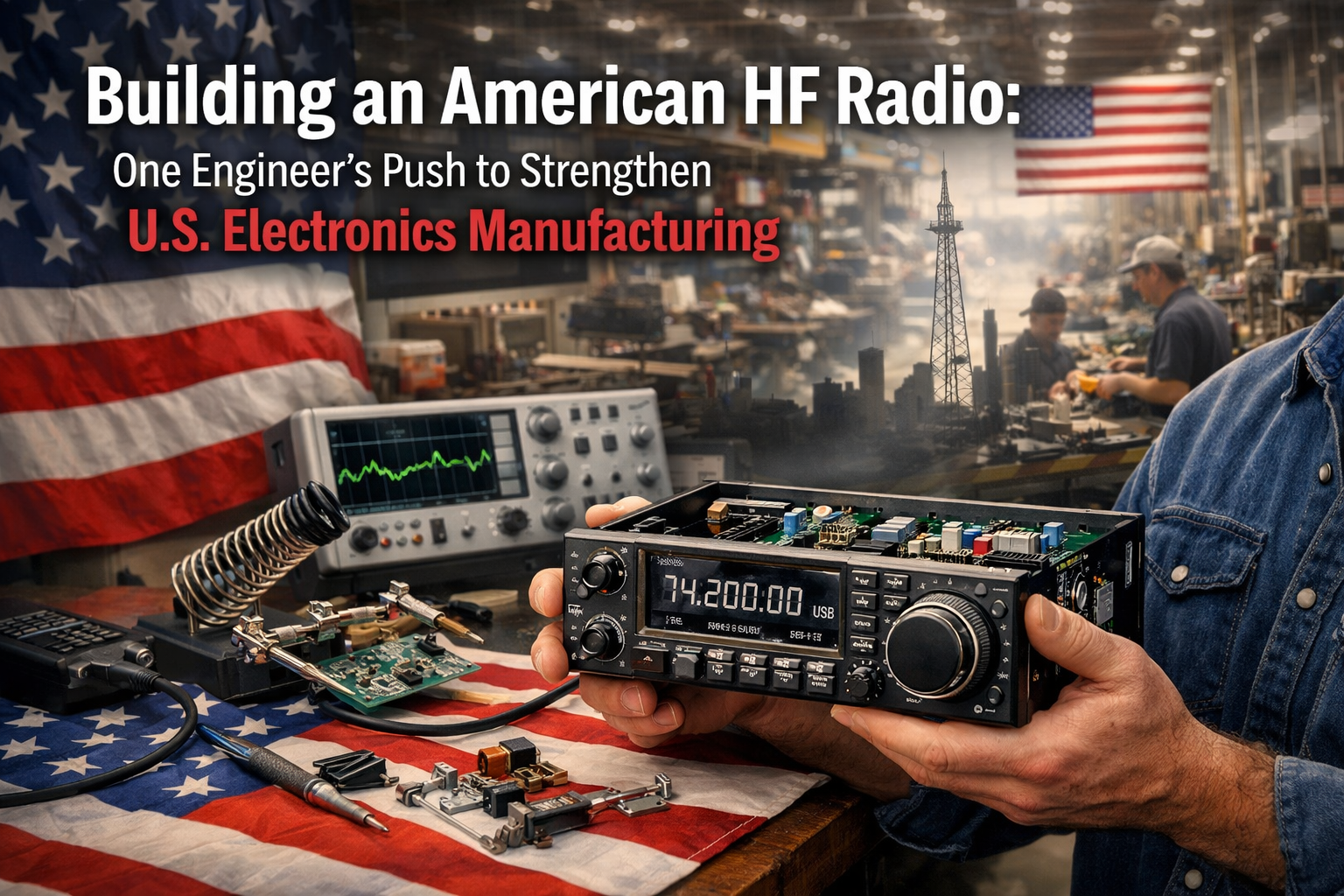
    We could strengthen U.S. Electronics Manufacturing with evolution of a U.S.-built HF SSB Transceiver. The United States is pouring historic investment into semiconductor fabrication, and that’s essential for national capability. But the layers above the silicon—RF design, analog engineering, PCB layout, assembly, testing, and small‑batch manufacturing—are just as critical. They’re where ideas become devices, where engineers learn by doing, and where innovation doesn’t require a billion‑dollar cleanroom.

    That’s the layer I’m stepping into with everything I’ve got.

    I’m building an HF radio from scratch in the U.S., and I’m doing it with full transparency about the partners who make it possible. I’m not a giant corporation. I’m the new guy—the nascent partner in a re‑emerging American electronics ecosystem. But I’m pushing hard, and I can see the path forward.

    🛠️ The early foundation: real partners, real parts

    Every project starts with a supply chain, and mine is built on companies I trust:

    • Mouser for foundational components, authorized sourcing, and predictable quality
    • Coilcraft for inductors that behave exactly the way RF filters demand
    • Amazon for miscellaneous parts, tools, and materials—origin unknown, quality verified
    • PCBWay for fast, consistent PCB manufacturing during the prototyping phase

    These aren’t anonymous vendors. They’re part of the story. They’re the reason my early boards exist, the reason my filters resonate where they should, and the reason I can iterate quickly.

    🇺🇸 Why the U.S. needs more than fabs

    Chip fabs are vital, but they’re not the whole picture. The U.S. also needs:

    • U.S. Electronics Manufacturing (small companies that can support markets at first)
    • Engineers who can design RF circuits
    • Technicians who can assemble boards
    • Small labs that can prototype quickly
    • Companies that can build specialized hardware in low to medium volumes
    • U.S. Electronics Manufacturing needs workplaces where Americans solve hands‑on technical problems

    This is the layer where a single engineer can make a difference. This is where small companies grow into meaningful contributors. This is where I want to build something real.

    📡 The HF radio as a proving ground

    My HF radio project isn’t just a hobby. It’s a forcing function—a way to build capabilities that scale:

    • High‑Q inductors for 160 m and 10 m filters
    • Stable, low‑noise RF amplification
    • Clean, reproducible PCB layouts for multi‑band RF paths
    • Repeatable assembly processes
    • Documentation that others can follow

    Every solved problem becomes a skill. Every skill becomes part of a future U.S. Electronics Manufacturing workflow.

    This is how a one‑person lab becomes a small manufacturer.

    U.S. Electronics Manufacturing

    🌱 The long‑term vision

    I want to grow into a U.S. electronics design, assembly, and U.S. Electronics Manufacturing company that:

    • Builds RF hardware with care and transparency
    • Manufactures boards domestically whenever possible
    • Partners openly with global suppliers
    • Creates challenging technical jobs for Americans
    • Strengthens the layers of the electronics ecosystem that sit above the silicon

    I’m not trying to compete with semiconductor fabs or big manufacturers. That’s not my lane, and it never has been.

    What I’m building lives in the layer those fabs make possible — the part of the process where real innovation actually happens. It’s the space between raw silicon and a finished product, where radios are thought through, designed, tested, and built one hard decision at a time.

    That’s where Freedom7, my HF transceiver project, lives. Not on a factory floor and not in a boardroom, but at a workbench — where schematics turn into boards, code meets copper, and performance is earned through testing and iteration.

    This is the part of engineering you can’t rush, outsource, or fake. It’s where ideas either work or they don’t. And it’s the kind of work I know how to do, because it’s how I’ve always done things.

    This is early. This is small. But it’s real. And I’m pushing hard because I can see what it could become. I’m excited about the influx of investment here and I see a bright future for U.S. Electronics Manufacturing maybe on a smaller scale than the AI chip fabs.

    I’m a real person, find about me, my character, my personality, my integrity at Facebook.

    A little more about my dream and why here.


    My About page provides the background of my project, the Freedom7 HF Transceiver.

    If this story resonates, comments are welcome. You can also reach me at david [at] kr4bad-dot-communications. no com

    And if you believe understanding matters more than black boxes, you can subscribe to my WordPress https://kr4bad.com/?subscribe=1.

    73 KR4BAD David

  • Why I’m Building My Own HF SSB Transceiver

    Why I’m Building My Own HF SSB Transceiver

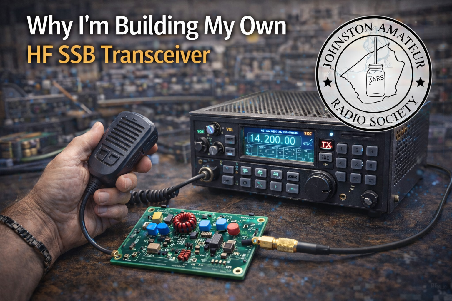
    Every radio operator has a moment when the hobby stops being just about making contacts and starts being about understanding what makes those contacts possible. For me, that moment arrived this past year and when I renewed my FCC license. I used to be KJ4GIZ long ago and that call had expired.

    I’ve been on the air for a while, but I realized something: I could operate an HF Single Side Band transceiver… yet I couldn’t explain one to others. Not really. Not down to the level where I could point to a signal path and say, “This is where the magic happens.”

    So I decided to build one.

    Not buy one. Not assemble a kit. Actually build one — stage by stage, circuit by circuit — until I could look at the finished radio and say two things with complete honesty:

    1. I finally understand how an SSB transceiver works.
    2. I made this myself.

    That second part matters more than I expected. There’s something deeply satisfying about the idea that when someone hears me on the air, they’re hearing a signal that came from a radio I built with my own hands. It’s like catching a fish with a lure you carved yourself — the contact means more because you made the tool.

    And yes, I’ve had help. Not from a mentor sitting next to me at a workbench, but from a different kind of companion: Microsoft Copilot. I’ve been using it to check circuit theory, explore design options, understand mixer behavior, and even sanity‑check my math. It’s been like having a patient, knowledgeable Elmer available 24/7 who never gets tired of my questions.

    But the deeper question — the one I want to share with the JARS (Johnston County Radio Society) members — is this:

    Why does this matter to my radio club?

    Because this project isn’t just about me. It’s about us.

    • It reminds us that amateur radio is still a hands‑on, experimental hobby. We don’t have to be just consumers of equipment. We can still be builders, tinkerers, experimenters — the very spirit amateur radio was founded on.
    • It shows that learning the fundamentals is still exciting. Understanding how SSB works isn’t just academic. It makes you a better operator, a better troubleshooter, and a more confident communicator.
    • It demonstrates that modern tools can empower old‑school skills. AI doesn’t replace the soldering iron. It just helps you understand what you’re soldering and why it matters.
    • It has shown that electronic projects today can be controlled with microcomputers. Modern electronics has seriously advanced beyond my school education. This project gives me a reason to own the ARRL Radio Handbook
    • It might inspire someone else in the club to build something too. Not necessarily a full transceiver — maybe a filter, a tuner, a preamp, or even a simple oscillator. But one person building something often sparks another.

    In February, when I stand up at the club meeting, I won’t just be showing off a radio. I’ll be sharing a journey — one that blends curiosity, craftsmanship, and a little help from a digital friend.

    And when I finally make that first contact on the air, I’ll be able to say:

    “You’re coming through loud and clear… on a radio I built myself.”


    My About page provides the background of my project, the Freedom7 HF Transceiver.

    If this story resonates, comments are welcome. You can also reach me at david [at] kr4bad-dot-communications. no com

    And if you believe understanding matters more than black boxes, you can subscribe to my WordPress https://kr4bad.com/?subscribe=1.

    73 KR4BAD David

  • Modular

    Modular

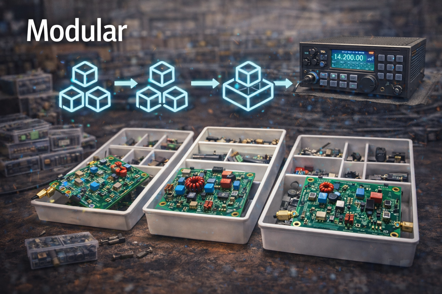
    The Freedom7 HF Transceiver has yet to receive or transmit however, I’m making progress and I’m designing components in a modular fashion. The image here below in this post shows my solution to Receive and Transmit switching. The screw terminal block on the side of the PCB has 4 connections for 5v, ground, receive digital, and transmit digital. The two RX/TX connections will be HIGH/LOW or LOW/HIGH respectively at any time.

    RX/TX Switching

    This is but one module called RX/TX Switching and it’s made to perform one task. This module will act as a stand-alone design that could be improved and replaced with a better module at a later time. I will share that I’ve done one PCB earlier e.g. with no screw terminals but later realized that solder pads were not supportive of a true modular concept. This is a work in progress. Future PCBs will be easy to implement and change out. Also note that a production-ready version of Freedom7 will probably be much different in high-level design. These modules will support my Freedom7 working prototype.

    I’ll share an early schematic but talk to the upper part of this. There are two MOSFETs that act as a 28v switch. Where did we get 28 volts you may ask? Well, I used a boost regulator MT3608 that converts 5v to 28v, with the help of a variable potentiometer. Either side will be biased at any time, i.e. the 1N5711 Schottky diode will be reverse-biased with 28v at the cathode side of the diode, thereby greatly blocking the flow of RF. This is not perfect but the small leakage that can occur is also choked with a 10 microhenry inductor and 3.3k resistor. I have calculations on these values. P.S. I also should call the digital control inputs just RX_BIAS and TX_BIAS.


    My About page provides the background of my project, the Freedom7 HF Transceiver.

    If this story resonates, comments are welcome. You can also reach me at david [at] kr4bad-dot-communications. no com

    And if you believe understanding matters more than black boxes, you can subscribe to my WordPress https://kr4bad.com/?subscribe=1.

    73 KR4BAD David

  • Control

    Control

    This project has been fun so far, but it’s hard to see the final, working product. I began this journey with the Arduino Nano R3 to be my choice of digital microcontroller. With the Nano, one can create it’s firmware using the Arduino IDE on any computer. The Arduino Nano is very popular, I got 3 of them on Amazon for like $13 with USB cables. I was hooked. I had a little computer that I could program with digital pins I could use to control things for my radio. I had my microcontroller.

    I initially had visions of 7 bands, 10m, 15m, 17m, 20m, 40m, 80m, and 160m. I also needed a way to push a button or cycle through a single button to select my band. A computer program, called a sketch for the Arduino, could monitor digital pins that are grounded with a momentary switch. A loop method or cyclic listening function would monitor 7 digital pins and then do something else based on the grounded pin. With the selection of these 7 pins, they are now reserved for this radio operation function or band selection.

    The Arduino has analog and digital pins. Some of the analog pins can be made digital but the digital HIGH is labeled floating. Normally the digital pin would be HIGH or 5V but for the analog pin it can drift. The solution is a pull-up resistor and 5V applied. The values are based on pin usage so I’ll not discuss that here. I will however, say that the digital pins are priceless because they can be used as sensors (incoming, grounded, sensing, etc.) or they can be digital representation. The analog pins can be used as sensing too but in an analog way, i.e. they can sense variations from 0 volts to 5 volts.

    I have tested a makeshift VFO with a single frequency. I have wired and tested an encoder with this VFO where 4 pins are used on the Arduino that do not interfere with the band select pins. Two pins are currently used to connect with another microcontroller, the Arduino Mega 2560. These pins are serial transmit and serial receive. Two pins are currently used for the I2C protocol. I have tested those with a programmable clock generator chip Si5351a that uses the two pins to send an address and then communicate with that device. The two pins on the Arduino can be an I2C bus if the pins are held high with the right pull-up resistors. I’ve tested continuous frequency memory with each band. I have three dedicated pins for addressing of RF switches.

    I also need more pins which I do not have for new features that have not been designed and tested. I ordered a breakout board with the MCP23017 GPIO extender that will give me 16 more digital pins for use with the Arduino. I have not tested it yet. Enter light bulb moment.

    Look at this post’s featured image and notice the Arduino Mega, shield and TFT display. Notice the convenience board with screw terminals around three sides. Notice the only two wires. They are serial transmit and receive. You can’t see the ground from the Nano in the photo. Well, you can see that wire crossing over the shield. Only three wires into the complex being. And, notice the little lower life form to the left. You don’t see the momentary select wires into the terminals but all the pins are reserved for something.

    Could the Arduino Mega be used for everything and can I use just one complex life form? Yes.

    I’ll take an aside on this post to tell you that I’m focused on modular components for my radio. I’ve also made some solid PCBs, i.e. I’m satisfied that they meet my requirements for the proof of concept (POC). But I’m glad that I’ve only done some draft schematics for the controller and display focus.

    UPDATE: I’m not going to re-write this posting but I’m now using two Arduino Mega 2560 microcontrollers, one solely for display and the other strictly for control.


    My About page provides the background of my project, the Freedom7 HF Transceiver.

    If this story resonates, comments are welcome. You can also reach me at david [at] kr4bad-dot-communications. no com

    And if you believe understanding matters more than black boxes, you can subscribe to my WordPress https://kr4bad.com/?subscribe=1.

    73 KR4BAD David

  • Document

    Document

    The Freedom7 HF Transceiver project really consists of multiple projects. One is pure design and experimentation. Another is product assembly, manufacture, and evolution. Lastly, an overlooked but oh so important project of documenting, accounting, journaling, recordkeeping, and just describing the parent project in detail for well-informed progress, decision-making assistance, and reduced anxiety moving forward.

    I generally push into new design and experimentation with ease. Yet, I begin to stress when it comes to assembling a vision of the completed product. And, I almost paralyze at the thought of documentation for something I’ve figured out completely. I am currently procrastinating the documentation for the first components I’ve completed and tested. These are passive LC band-pass filters.

    With this post, I’ll outline how I plan to break this procrastination and do each component’s documentation. I have been using Donald Knuth’s TeX typesetting system to produce my most important and formal documents. I’ll share my outline for breaking this procrastination and also produce a PDF sharing my band-pass component’s TeX documentation.

    Here are the numbered but unordered considerations for documenting each Freedom7 HF Transceiver component:

    1. Series of iterations of component on paper from simple box to full detail
    2. What is it and what does it do?
    3. What are its interfaces?
    4. Does it need power? Voltage? Amperage need?
    5. Active or Passive and why? Pros and cons?
    6. Does it need outside (external) control, configuration, tuning (once or operator), etc?
    7. Does it require testing, tuning during manufacture, adjustment, trials, reset (internal or operator), etc.
    8. Shielding?
    9. Ground plane concerns?
    10. Possible floating pins?
    11. Consists of the following parts? Footprints for PCB? Costs?
    12. Calculations, modeling (LTSpice), paper trials, etc. or any deep technical analysis?

    Here’s an example TeX document that’s unfinished. I’ll add the considerations shown above and replace this when the formal document is complete. This is provided here to show the type (TeX) of document I’ll use to reference each component as I go.

    Loader Loading…
    EAD Logo Taking too long?

    Reload Reload document
    | Open Open in new tab

    My About page provides the background of my project, the Freedom7 HF Transceiver.

    If this story resonates, comments are welcome. You can also reach me at david [at] kr4bad-dot-communications. no com

    And if you believe understanding matters more than black boxes, you can subscribe to my WordPress https://kr4bad.com/?subscribe=1.

    73 KR4BAD David

  • Reference

    Reference

    Hilberling PT-8000A

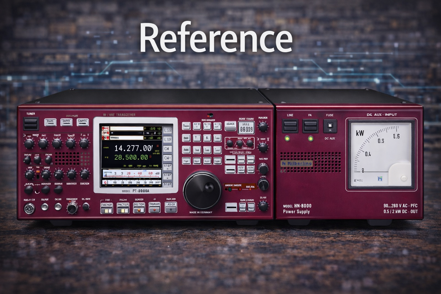
    No, it’s not the Freedom7, but it’s what I would consider the reference specification for measuring the quality of an HF transceiver. The radio you see above is the Hilberling PT-8000A. I’m sharing this because I needed something to guide my ideas for the Freedom7 HF Transceiver that’s my current DIY/Homebrew project. I use this radio like I’ve used things that my father has created to help me judge the quality of things that I have made with my hands.

    This post is to describe how I will move from inception of the Freedom7 to a physical radio, sitting on my desk, and fully operational. And, where my HF radio is a DIY effort, I continually look at the best-in-breed radios for inspiration during this effort.

    I also want to share my architectural strategy here. This strategy is mentioned briefly on the bottom of this blog’s main landing page. These three concepts are: Component, Interfaces, and Testability. This radio is a huge undertaking but I am an Enterprise IT Architect by trade and my mind immediately goes to a division of the whole into bite-sized chunks. These chunks are really components. Look at the Hilberling radio above and what do you immediately see as a component? I see a Power Supply. Okay, that’s component 1. Other components may be more difficult to see. Ask yourself how you saw the Power Supply as a component? It’s because the Power Supply has visible boundaries. It’s in its own enclosure. You can just see it visibly as being it’s own component. This is but one needed component for the Freedom7 HF Transceiver. We will need power to light all of the components.

    I’ll just mention a few other components and then I’ll describe the importance of Interfaces. We’ll need band pass filters, a VFO, mixer, modulator, demodulator, amplifiers, RX/TX switching, filter selection, display, control systems, and more. Instead of focusing on specifics, I mainly want to emphasize that the radio is comprised of a collection of components. And, these components have boundaries and contexts. But most importantly, these components communicate, are powered, and are controlled or configured through interfaces.

    Components are bounded by context, borders, boundaries, edges of PCBs, lol, something that keeps the context within. My point is that every component can be defined as a functional item that does something to contribute to the overall operation of the HF transceiver. These components all have some form of interface. These interfaces are analogous to wires that may be coming from a black box. If the black box is the component we know that something happens within the black box and the wires would be the only way in or out of the box. These wires or interfaces have a function and a protocol for how they are used.

    Let’s discuss the component interface and how it’s modeled for any HF radio component. Remember that these components can be modeled on paper, along with their interface definitions, and then we can answer questions like 1) is it testable? 2) how would we test it? We’ll discuss that next but think about the component and how it must have interfaces of some kind.

    I’ll describe the band pass filter as a component and only describe this (sub) component at a high level with a single sentence. We’ll analyze the sentence and then define its interfaces. The Freedom7 band pass filter is a passive LC design that accepts RF at the width of the ARRL HF spectrum or 1.8-30 MHz and allows a narrower bandwidth with roll-off of approx. -40 dB on both sides of the narrowed bandwidth and minimal insertion loss (approx. -6 dB) across the translated bandwidth. That’s quite a mouthful but it tells me a lot about this new black box I need for my new Freedom7 HF Transceiver.

    The Freedom 7 HF Transceiver will support 7 bands across the ARRL accepted HF spectum, 1.8-30 MHz. These are 10m, 15m, 17m, 20m, 40m, 80m, and 160m. Given 7 bands, we’ll need 7 bandpass filter components for receive and 7 bandpass filter components for transmit. I’ll now describe the interfaces for each bandpass filter. Since the filters are passive, they do not require power. Each filter consists of 3 series LC traps with additional drop capacitors to shape and narrow the bandwidth. The filters are simple with RF in and RF out. Two interfaces per filter.

    I used the Freedom7 bandpass filter as a component example only and to show that the component has a single function and two simple interfaces, radio frequency in and out. With the component and interfaces defined, we can now ask if the component is testable and give an analysis for testing.

    First, yes, the bandpass filter is testable. Each bandpass filter needs an HF-wide RF signal and we need a way to see the shape of the dB cut over the width of the input signal. Designing each filter was done with the help of LTSpice and LTSpice can render the shape of the filter response. I’ll go into the design of components in other posts but just mention that LTSpice was used early-on to provide expectation for this analysis (testing) I’m discussing here. The Nano VNA is a popular spectrum analyzer that I happen to own and it was used to show each filter response.

    I hope that I’ve clearly described the modular component architecture strategy that I’m using to create this DIY HAM radio I call the Freedom7. I’ll be posting detailed articles soon and I will follow the component, interface, and testability concepts with each component. This post was about reference and my goal was to share with you my quest for only the best quality using quality examples like the Hilberling and also reference to sound architecture practices. I just want to share with my HAM friends, my Freedom7 HF Transceiver and how I’m doing it. It’s exciting and I want to share. I hope that I can spark others to work with me in the future. I can’t afford the Hilberling, but I certainly can aspire to do it myself.

    P.S. Here’s a link to the Hilberling https://www.hilberling.de/en/hamradio/. My picture above is antiqued or filtered as part of this blog theme. I could have rendered it in full color but it’s not a post about the Hilberling; that’s just something to dream about Christmas eve.


    My About page provides the background of my project, the Freedom7 HF Transceiver.

    If this story resonates, comments are welcome. You can also reach me at david [at] kr4bad-dot-communications. no com

    And if you believe understanding matters more than black boxes, you can subscribe to my WordPress https://kr4bad.com/?subscribe=1.

    73 KR4BAD David