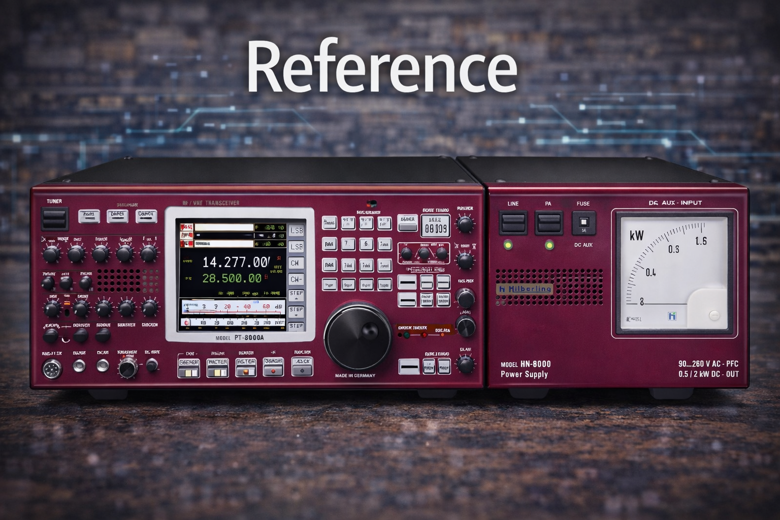

No, it’s not the Freedom7, but it’s what I would consider the reference specification for measuring the quality of an HF transceiver. The radio you see above is the Hilberling PT-8000A. I’m sharing this because I needed something to guide my ideas for the Freedom7 HF Transceiver that’s my current DIY/Homebrew project. I use this radio like I’ve used things that my father has created to help me judge the quality of things that I have made with my hands.
This post is to describe how I will move from inception of the Freedom7 to a physical radio, sitting on my desk, and fully operational. And, where my HF radio is a DIY effort, I continually look at the best-in-breed radios for inspiration during this effort.
I also want to share my architectural strategy here. This strategy is mentioned briefly on the bottom of this blog’s main landing page. These three concepts are: Component, Interfaces, and Testability. This radio is a huge undertaking but I am an Enterprise IT Architect by trade and my mind immediately goes to a division of the whole into bite-sized chunks. These chunks are really components. Look at the Hilberling radio above and what do you immediately see as a component? I see a Power Supply. Okay, that’s component 1. Other components may be more difficult to see. Ask yourself how you saw the Power Supply as a component? It’s because the Power Supply has visible boundaries. It’s in its own enclosure. You can just see it visibly as being it’s own component. This is but one needed component for the Freedom7 HF Transceiver. We will need power to light all of the components.
I’ll just mention a few other components and then I’ll describe the importance of Interfaces. We’ll need band pass filters, a VFO, mixer, modulator, demodulator, amplifiers, RX/TX switching, filter selection, display, control systems, and more. Instead of focusing on specifics, I mainly want to emphasize that the radio is comprised of a collection of components. And, these components have boundaries and contexts. But most importantly, these components communicate, are powered, and are controlled or configured through interfaces.
Components are bounded by context, borders, boundaries, edges of PCBs, lol, something that keeps the context within. My point is that every component can be defined as a functional item that does something to contribute to the overall operation of the HF transceiver. These components all have some form of interface. These interfaces are analogous to wires that may be coming from a black box. If the black box is the component we know that something happens within the black box and the wires would be the only way in or out of the box. These wires or interfaces have a function and a protocol for how they are used.
Let’s discuss the component interface and how it’s modeled for any HF radio component. Remember that these components can be modeled on paper, along with their interface definitions, and then we can answer questions like 1) is it testable? 2) how would we test it? We’ll discuss that next but think about the component and how it must have interfaces of some kind.
I’ll describe the band pass filter as a component and only describe this (sub) component at a high level with a single sentence. We’ll analyze the sentence and then define its interfaces. The Freedom7 band pass filter is a passive LC design that accepts RF at the width of the ARRL HF spectrum or 1.8-30 MHz and allows a narrower bandwidth with roll-off of approx. -40 dB on both sides of the narrowed bandwidth and minimal insertion loss (approx. -6 dB) across the translated bandwidth. That’s quite a mouthful but it tells me a lot about this new black box I need for my new Freedom7 HF Transceiver.
The Freedom 7 HF Transceiver will support 7 bands across the ARRL accepted HF spectum, 1.8-30 MHz. These are 10m, 15m, 17m, 20m, 40m, 80m, and 160m. Given 7 bands, we’ll need 7 bandpass filter components for receive and 7 bandpass filter components for transmit. I’ll now describe the interfaces for each bandpass filter. Since the filters are passive, they do not require power. Each filter consists of 3 series LC traps with additional drop capacitors to shape and narrow the bandwidth. The filters are simple with RF in and RF out. Two interfaces per filter.
I used the Freedom7 bandpass filter as a component example only and to show that the component has a single function and two simple interfaces, radio frequency in and out. With the component and interfaces defined, we can now ask if the component is testable and give an analysis for testing.
First, yes, the bandpass filter is testable. Each bandpass filter needs an HF-wide RF signal and we need a way to see the shape of the dB cut over the width of the input signal. Designing each filter was done with the help of LTSpice and LTSpice can render the shape of the filter response. I’ll go into the design of components in other posts but just mention that LTSpice was used early-on to provide expectation for this analysis (testing) I’m discussing here. The Nano VNA is a popular spectrum analyzer that I happen to own and it was used to show each filter response.
I hope that I’ve clearly described the modular component architecture strategy that I’m using to create this DIY HAM radio I call the Freedom7. I’ll be posting detailed articles soon and I will follow the component, interface, and testability concepts with each component. This post was about reference and my goal was to share with you my quest for only the best quality using quality examples like the Hilberling and also reference to sound architecture practices. I just want to share with my HAM friends, my Freedom7 HF Transceiver and how I’m doing it. It’s exciting and I want to share. I hope that I can spark others to work with me in the future. I can’t afford the Hilberling, but I certainly can aspire to do it myself.
P.S. Here’s a link to the Hilberling https://www.hilberling.de/en/hamradio/. My picture above is antiqued or filtered as part of this blog theme. I could have rendered it in full color but it’s not a post about the Hilberling; that’s just something to dream about Christmas eve.
My About page provides the background of my project, the Freedom7 HF Transceiver.
If this story resonates, comments are welcome. You can also reach me at david [at] kr4bad-dot-communications. no com
And if you believe understanding matters more than black boxes, you can subscribe to my WordPress https://kr4bad.com/?subscribe=1.
73 KR4BAD David


Leave a Reply