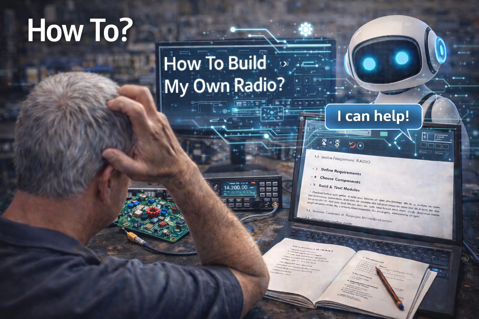

My technician class license renewal was pretty easy and I struggled a bit before my general. The vision of a DIY Ham radio came through my brain, quite obnoxiously, interrupting my study for my extra about 2 weeks after I paid ARRL too much for a study guide. Now just after the ADHD kicked in, the real question was, “How am I going to make my own HF radio?” or “How-to?”.
I’m here to tell you the answer to the how-to question is easy. AI is not your enemy. In fact, I wish that I had AI when I was in college. I would be addressed as Dr. Whitehurst today. But beware because with everything AI gives you, it comes with no shame, no caveat, no hesitation, etc. You can’t accept all AI responses as truth or gospel. You can however, use it to accelerate the creation of a DIY HAM radio.
I’m going to use the post image to describe how I used AI to arrive at my design and how I chosen components to accomplish a task within the larger component of RF routing into selected band-pass filters. I first want to make this analogous to fishing. And, if I didn’t catch the big fish it was because “you’re not holding your mouth right” according to my dad. With AI, you’re not going to get the best answer when “you didn’t give it the right prompt”. Let’s begin a session with AI and I’ll you’ll begin to see how this fishing trip goes.
I’ll provide a background to describe the need for the circuit above and we’ll begin just after the requirements. The Freedom7 HF Transceiver decidedly selected 7 bands, 10m, 15m, 17m, 20m, 40m, 80m, 160m for use. I now knew that I would have 7 bandpass filters. I could see my seven filters just after the antenna came into the radio enclosure. Wait a minute, we need a splitter of sorts and really a switching mechanism because our RF doesn’t need to be wasted on all filters. We have this weak RF signal and we need to route it through a band-pass filter and selectively narrowing the spectrum to the band chosen by the radio operator.
We now need to think of components, interfaces, and testing. I could see this thing or black box with one RF input and seven outputs. These interfaces would be SMA. Easy right? So what exactly does this black box need beyond the single input and then outputs into each band-pass filter? How do we select or switch into the output SMA? I could think of two choices: 1) mechanical switch or 2) digital selection. I liked the digital selection because that’s what I learned most about in school. Enter AI.
I’ll skip over the part here where the radio operator will push a momentary switch for the selection of one of the seven bands. Assume that we are using microcontrollers inside and when the operator pushes the button for 20 meters that the microcontroller can send the information needed to drive a chip to route the RF signal to a unique RF output. Let’s now ask AI (Microsoft CoPilot) if there are available chips to route RF signals. We’ll ask the question and I’ll share the AI response here. Ask AI very clearly what you want. And, if backstory is needed give it.
Here goes … Prompt: I’m making a homebrew HF transceiver. The RF ranges between 1.8 and 30 Mhz. Are there IC chips that can route input RF to many outputs based on digital selection?
CoPilot Response: Yes, there are RF switch ICs that can route signals in the 1.8–30 MHz range to multiple outputs using digital control. These are typically SPxT (Single-Pole x-Throw) switches designed for wideband applications.
🔌 Recommended RF Switch ICs for HF Transceivers
Here are some ICs suitable for routing RF signals in your HF range:
| IC | Type | Frequency Range | Control | Notes |
|---|---|---|---|---|
| ADG904BRUZ | SP4T | DC to 2.5 GHz | CMOS | Absorptive switch with low insertion loss analog.com |
| ADRF5051 | SP4T | 9 kHz to 20 GHz | CMOS | Nonreflective, high isolation analog.com |
| ADRF5060 | SP3T + Bypass | 100 MHz to 20 GHz | CMOS | RF path selector, may need bandpass filtering analog.com |
| PE42422 (pSemi) | SPDT | 10 MHz to 8 GHz | CMOS | High linearity, low loss pSemi |
| Mini-Circuits USB-RF Switches | SPDT–SP10T | DC to 50 GHz | USB/digital | Modular, ideal for test setups Mini Circuits |
Sources: Mouser Electronics analog.com pSemi Mini Circuits
🧠 How to Use These in Your Design
- Digital control: Most switches use CMOS logic (e.g., 3.3V or 5V) for selection.
- Routing options: Choose SP4T or SP6T depending on how many outputs you need.
- Insertion loss: Look for <1 dB to preserve signal strength.
- Isolation: Higher isolation (>30 dB) prevents crosstalk between outputs.
- Absorptive vs Reflective: Absorptive switches terminate unused ports to prevent reflections—ideal for RF.
🛠️ Application Ideas
- Band switching: Route different frequency bands to separate filters or amplifiers.
- Antenna selection: Switch between multiple antennas based on mode or band.
- Signal routing: Direct RX/TX paths to different modules or test points.
Would you like help selecting a switch for a specific number of outputs or integrating one into your schematic?
End CoPilot
I did not edit the CoPilot response but you notice that the ADG904BRUZ chip was first in the list. I knew nothing about this chip until I asked AI. I held my mouth right that time, and caught the big fish. I knew that my next step was to find my Golden Field Guide to Fish and look him up. Or, better yet search for a datasheet on the ADG904BRUZ chip.
My microcontrollers are being used for various tasks but they both (yes 2) are powered by 5V. This chip requires a step-down regulator.
 Loading…

 Reload document
  Open in new tab
 I’ll not belabor this post with all of my design details here but I do want to emphasize how important AI can be in figuring all this out. I’ll leave you with some homework. Ask Copilot how two ADG904BRUZ chips could be used with a microcontroller to drive the choice of 7 unique RF outputs. You will be amazed. Just ask it your question.
I’ll end my post today with the following. AI is not always right. I have caught outright untrue responses/results. I have also called AI on these facts and AI provided a second look and agreed with cause for debate. I’ll write more about this in the future. AI is here so use it for what it is. Learn, learn, … and learn some more.
My About page provides the background of my project, the Freedom7 HF Transceiver.
If this story resonates, comments are welcome. You can also reach me at david [at] kr4bad-dot-communications. no com
And if you believe understanding matters more than black boxes, you can subscribe to my WordPress https://kr4bad.com/?subscribe=1.
73 KR4BAD David
Leave a Reply